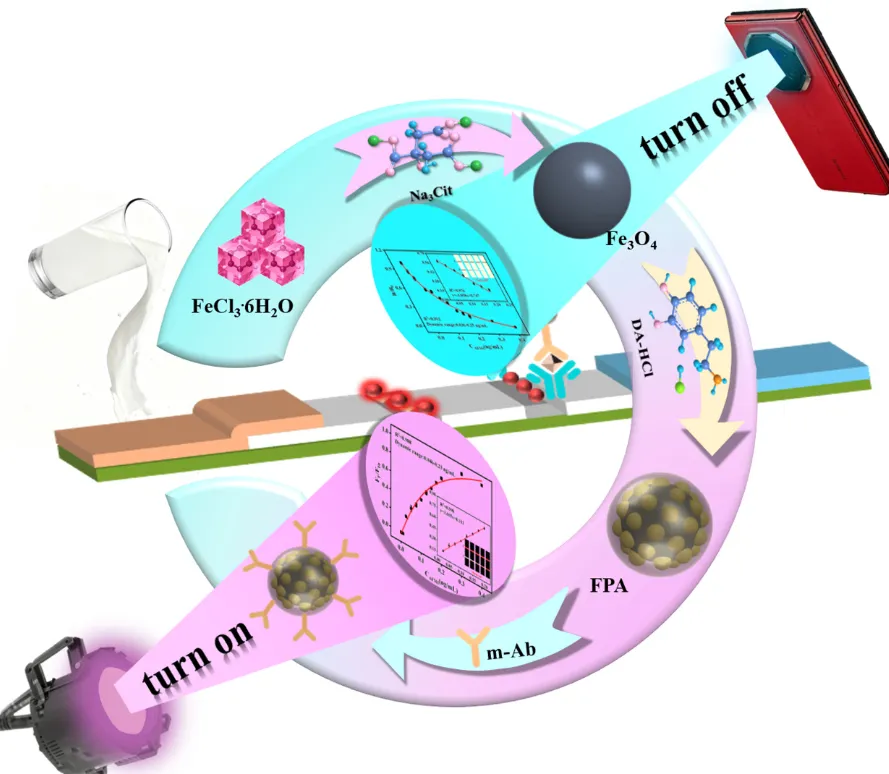
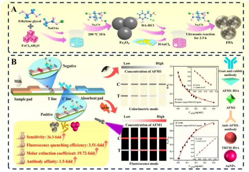
Scheme 1. Schematic diagram of the FPA-LFIA; (A) Synthesis of FPA; (B) Detection principle of FPA-LFIA and comparison of the properties between FPA and AuNPs.
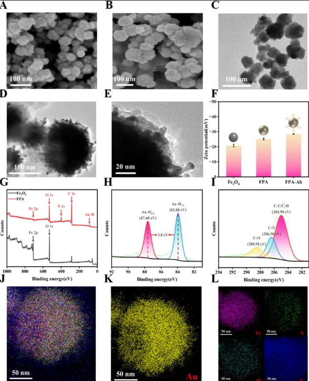
Fig. 1. SEM images of (A) Fe3O4, (B) FPA. (C) TEM image of Fe3O4. (D, E) HRTEM image of FPA. (F) Zeta potential of Fe3O4, FPA and FPA@mAb. (G) XPS curves of Fe3O4 and FPA. (H) Au 4f peaks in FPA composites. (I) C 1s peaks in FPA composites. Elemental mappings of FPA (J), Au in FPA (K) and Fe, N, O, C in FPA (L).
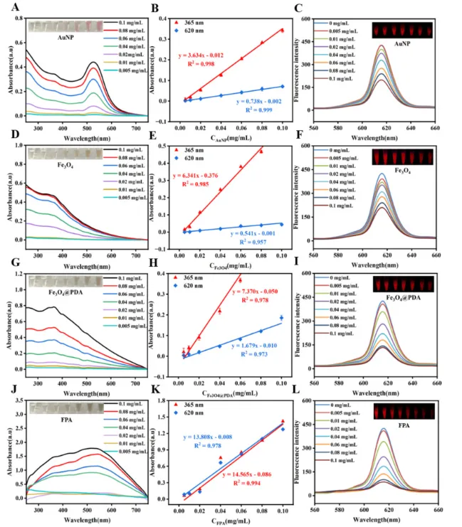
Fig. 2. Calculation of the absorption coefficient and fluorescence quenching constant. UV–vis absorption spectroscopy of (A) AuNPs, (D) Fe3O4, (G) Fe3O4@PDA, and (J) FPA. Absorption coefficient calibration curves of (B) AuNPs, (E) Fe3O4, (H) Fe3O4@PDA, and (K) FPA. Fluorescence spectra of TRFM (100 μL, 0.04 mg/mL), which decreased at 620 nm with the addition of AuNPs (C), Fe3O4 (F), Fe3O4@PDA (I), and FPA (L).
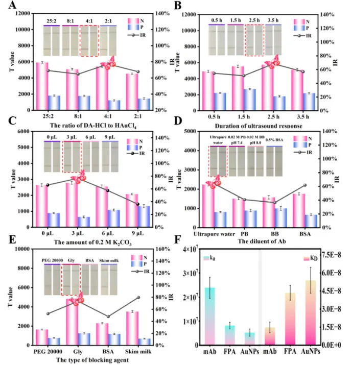
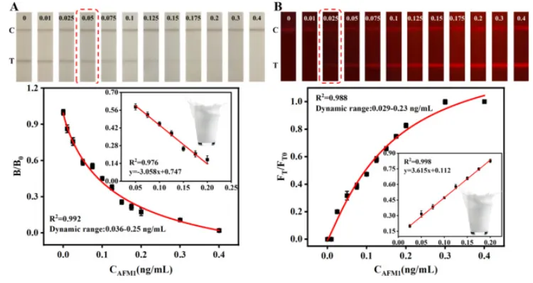
Fig. 3. Optimization of FPA-LFIA material synthesis parameters and labeling conditions: (A) the ratio of DA-HCl to HAuCl4, (B) the duration of ultrasound response, (C) the amount of 0.2 M K2CO3, (D) the diluent of Ab, (E) the type of blocking solution, (F) Comparison of ka and KD.Fig. 4. Photographs and calibration curves of the FPA-LFIA strips. The colorimetric signal (A), and fluorescence signal (B).


 10个月宝宝每天需要喝多少奶粉?
